OMSynth
Invent your new sound, at home or on the go
Perhaps you've long wanted to create a minimal lo-fi tune. Perhaps you've always yearned to become an evil genius and take over the world – with a massive beat as your soundtrack. No matter the case, the OMSynth miniLab is ready to provide whatever tools you might need.
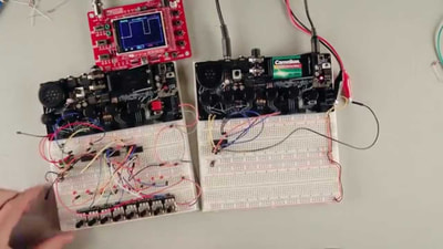
The OMSynth is a circuit development and performance interface designed to help you quickly build audiovisual instruments from scratch and experiment with them live. While it keeps beginners in mind, it's best suited for those with some circuit building experience.
Enjoy the ultimate circuit lab experience
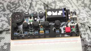
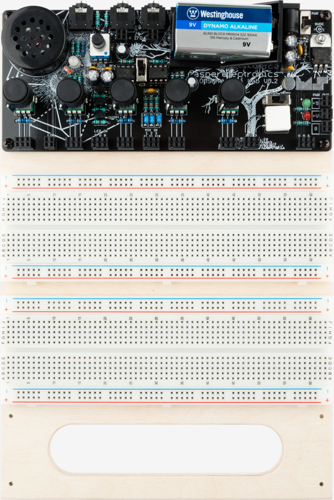
The OMSynth was developed by Casper Electronics, and it offers all you need to start inventing circuits to make sound and light just like Peter Edwards does. You'll have potentiometers, audio mixer, speaker headphone output, battery or adapter power, and more directly at your hands.
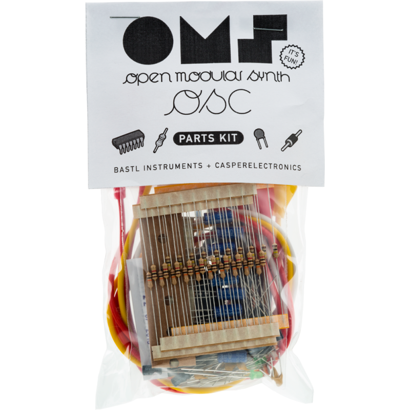
The OMSynth comes withtutorial videos for making analog oscillators, sequencers, and lo-fi digital sampler. It comes with OMSYNTH OSCILLATOR PARTS KIT for free!
What the OMSynth is and what it is not
The OMSynth IS a super useful circuit development tool that we have used as teachers and circuit developers to make our job more comfortable and fun. All the circuit development done by Peter Edwards at Bastl was possible thanks to the OMSynth, from early sketches to finished instruments like the bitRanger and the softPop.
The OMSynth IS NOT a beginners' electronics course. We have provided tutorial videos and parts kits (see below) for workshops to help beginners get into experimental circuit design quickly and ease them into more complex, often un-intuitive electronics principles. With that said, it will be absolutely necessary for beginner users to do additional research on their own.
Rather than giving ALL the answers upfront, the OMSynth is our way of equipping people with a powerful tool and a big boost of encouragement as they embark on the long strange audio circuit design journey. We welcome emails from those eager to move forward or simply want to share discoveries and excitement. Feel free to email pete[at]casperelectronics[dot]com.
Features
- Battery (included) or 9V wall wart power options (not included)
- Regulated 5V and unregulated power sockets
- over-current protection fuse (200mA) protects circuit from shorts or improperly installed ICs
- 3 channel audio mixer with individually weighted inputs (x1, x1 and x10)
- Amplified speaker with volume control
- Dual mono headphone output
- 2 stereo I/O jacks for connecting to external circuits, modular synths, etc
- Tri-color LED with discrete channel drivers
- Light sensor for light based variation of circuit parameters
- The light sensor is installed facing the LED making it a basic vactrol (voltage to resistance converter)
- 3 touch sensors (the OMS logo) for touch based manipulation of circuit parameters
- 5 modular 100k potentiometers (protected by 1k buffer)
- 1 modular pushbutton and integrated on/off switch
- 2 full size breadboards
- Laser engraved base plate with a carrying handle
- Expansion section for adding control boards or custom circuits
DIY kit
You can build your own OMSynth with our DIY kit. Go through the complete assembly guide below and make sure that you understand all the steps.
- DIY KIT DISCONTINUED
- complete assembly guide pdf v3.2 update pdf v3.2
- bill of materials googledocs
- schematics pdf
- board diagram pdf
Satellite Hardware Boards
In addition to the on-board features listed above there are also a range of hardware boards available for installing addition control hardware to your circuit.
- potentiometers (available in a range of values).
- slide switches
- pushbuttons
Expansion Boards
At the bottom of the OMSynth miniLab is an expansion section intended for the inclusion of control hardware boards but can also be used by users to hold custom boards.
- 9 point touch contact board
- 8 channel sequencer pot board
- ribbon controller
A Note About Breadboards
The breadboard is a standard interface used for quickly building electrical circuits. This is a universal format which will accept nearly all electrical components. Most hardware (pots, buttons, switches, ect) will also fit in the breadboard but are extremely unstable and clumsy to use. Therefore we have designed the satellite boards (detailed above) to allow secure installation and use.
Inside the breadboard are sets of little metal fingers that grab onto component legs that are pushed into the holes. These are arranged in columns of 5 and horizontal rows of 50. The horizontal rows are generally intended for connecting your power supply so it can be easily connected throughout your circuit. The columns are for building your main circuit. A horizontal space in the middle separates the columns so that integrated circuits may be installed in the middle.
The Drawing below further illustrates the connections within the breadboard. It takes a bit of practice and discipline to build successful and dependable circuits, but with the right tools and some patience this can be a quick and effective process.
Using the OMSynth MiniLab
Use will depend entirely on the circuit being built and the experience of the user but here are the basic steps universal to most projects.
- The first step is to connect the power from the OMSynth to the power rails of the breadboard. This should be done with solid core wire and the wires should be neatly tucked away to avoid being accidentally unplugged. Typically one would connect the power (5VDC or unregulated) to all 4 red red power rails on the breadboards and ground to the 4 blue power rails.
- Next build your circuit on the breadboard using ICs and resistors, capacitors etc.
- Connect the circuit to the potentiometers and switches to add variable control.
- If you are building an audio circuit, connect the audio source to the input of the mixer. Make sure the amp power switch is ON if you want to use the onboard speaker.
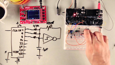
- In many circuits it will be useful to see the behaviour of certain signals like an LFO used to clock a sequencer for instance. In these cases connect the signal(s) to the inputs of the LED.
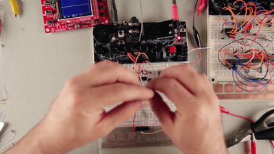
Breadboard Practice and Debugging
Despite your best efforts there will come a time that a circuit we have built simply won’t work. Debugging is an art form that takes patience, time and more patience. It can never be entirely avoided, but the need for it can be dramatically reduced through clean and methodical breadboarding practices… So the first step to debugging starts as you assemble the circuit. Clutter is the enemy and it will claim your circuit and your sanity if left unchecked.
When one is first starting to build a circuit it is easiest to plug components and wires into the board without sizing or trimming anything. This makes it easy to achieve fast results and allows easy reconfiguring as you go. But once parts of the circuit are established it is best to trim your components and wires to be flush to the board.
Eventually the entire circuit should be cleaned up in this manner.
The only exceptions being cases where changes to connections will need to be made with some regularity.
In these cases untrimmed components and longer wires should be used.
The next step to avoiding the need for debugging is to constantly monitor the functionality of your circuit while working on it. For instance don’t turn off the circuit then make a dozen changes before turning it back on. If there is a problem it will be hard to track where it occurred.
In any case despite your best efforts there will come a time that you are confronted with a circuit that simply doesn’t work. The solutions are varied but here are some universal steps to take.
- Make sure the OMSynth and amplifier power switches are on :)
- Check for any short circuits between component legs. This is the main argument for trimming the legs. But hey, we’re all human and we don’t always trim our component legs. Check this first. This is usually the problem.
- Check for loose wires. Has anything come unplugged? Like the power rails??
- If this is the first time powering up the circuit then check all the component values to make sure they are correct.
If functionality is intermittent then it is most likely caused by loose or faulty patch cables or touching component legs.
Beyond these steps debugging becomes a more involved process. Its important to imagine each functional element of your circuit as a discreet block. Now isolate and test each of these blocks. With some practice this way of thinking becomes intuitive and the process can go very quickly.
OMSynth Sections
Power
This section supplies voltages that you will need to power your circuit. The outputs are capacitively coupled (increases voltage stability) diode protected (protects against backward polarity) and fuse protected (up to 200mA. protects against short circuits).
- You can use the onboard 9volt battery or an external supply.
- Plugging in an external supply will disconnect the battery.
- The supply must supply a DC voltage between 7 and 35 volts but for most applications no more than 12 volts is needed.
- The supply must be negative ring, positive tip as indicated on the board.
The +V output is connected directly to the power supply (through the diode and fuse). If a higher voltage level is needed you can use an external power supply rated at the required voltage.
The +5 output will take any input between 7 and 35 volts DC and convert it to a stable 5 volts. This can be used for applications where 5 volts is required (microcontrollers for example) or where the unregulated power may be too unstable.
Mixer
The mixer has 3 inputs. The right most input will amplify the signal x10. The centre and left are un-amplified (x1). The amplified input is intended for low level signals such as sine and triangle waves.
Be aware that signals plugged into the x10 input may overpower the other two. The amplitude of the x10 input can be reduced to the level of the other two by adding a 10k resistor in series with the signal (actually a 9k but 10k are much more common and should work well enough for most applications).
Amplifier
The amplifier will take the signal from the mixer and amplify it to a level appropriate to drive the onboard speaker. If you do not plan to use the onboard speaker, the amplifier can be turned off with the amplifier power switch to conserve battery power (if batteries are being used).
Headphone Out
The headphone out jack can be used to send a mono signal from the mixer to external gear or a stereo (dual mono) signal to the headphones. Plugging a cable into the headphone jack will disconnect the signal from the input of the amplifier.
LED Section
This section has three buffered inputs which are routed to the three channels of a tricolour LED (red, green & blue).
The brightness of the LED is dependant on the voltage level of the incoming signal. Therefore the LEDs can be used to monitor signal levels within your circuit.
LDR (Light Dependant Resistor)
The LDR has two inputs. The resistance between these points will vary (approx. between 10k ohms and 1M ohms) as the light which falls on the light sensor increases and decreases.
More light = lower resistance.
The LDR is installed facing the LED. Voltages applied to the LED will increase the brightness which will in turn reduce the resistance of the LDR. This combination of LED and LDR is commonly known as a vactrol and is a classic method of converting voltage to resistance. This effectively lets you add voltage control to nearly any circuit. Unlike the traditional vactrol, this one is not sealed which means ambient light will also effect the LDR. This was done to allow maximum flexibility of how the LDR is used. If you would like to use the LDR independently from the LED, a light blocking piece of material can be placed between the LDR and LED. If you would like a more traditional vactrol configuration you can place black tape or something similar over both the LED and LDR to block out ambient light.
Touch Pads
This section has three sockets connected to the three letters of the OMS logo respectively.
These can be connected to circuits which are sensitive to touch and manipulated by placing your finger on the sensors.
Potentiometers
Each of the 5 potentiometers have three connection points connected to the three legs of the potentiometer. The pots are rated at 100k ohms and have a 1k resistor in series with the centre pin to avoid short circuits to the power which can damage the conductive material inside the pot.
Switch / Button
This section has three connection points connected to both the switch and the button.
Pressing the button connects points 1&3. (see drawing)
Throwing the switch to the right connects 2&3. To the left connects 1&2. This slightly unconventional configuration allows the user to make patches which can be manipulated with both the switch and button simultaneously.
For instance in the image to the right connecting the power supply through the switch allows the user to pulse the power on and off by pressing the button or to turn it on and off with the switch.
Video