This is part three of a three part series on DIY synth building. If you’re brand new to electronics I strongly recommend you watch them in order!
Part 1: Oscillators
Part 2: Sequencers
Part 3: LoFi sampler and voltage controlled filter
This is a super cool little looper/sampler project based around the ISD1820 “voice recorder” IC. It’s dirty and clicky and generally crappy but I’ve found it to be a surprisingly endearing circuit to play with. Just after filming the tutorial I realized it could also be used as an equally crappy but totally effective low pass voltage controlled filter! An unexpected feature from a cheap lil’ voice recording chip :) I’ve put info on that here.
For this project you will need:
- CD40106 Schmitt trigger IC
- CD4040 Binary counter/clock divider IC
- ISD1820 Voice recording IC. These may be hard to find in shops, but a quick ebay search will give you lots of options.
- 1k, 10k, 47k, 100k, 470k, 1M resistors
- 100k potentiometers
- 0.1uF, 1uF, 10uF capacitors
- a breadboard or two
- a 5volt power supply or 9volt battery with a 5volt regulator like the L78L05
- lots of jumper wires
- alligator clips and some kind of metal objects to clip to in order to make a touch panel for controlling the pitch of the sample.
Building a basic sampler
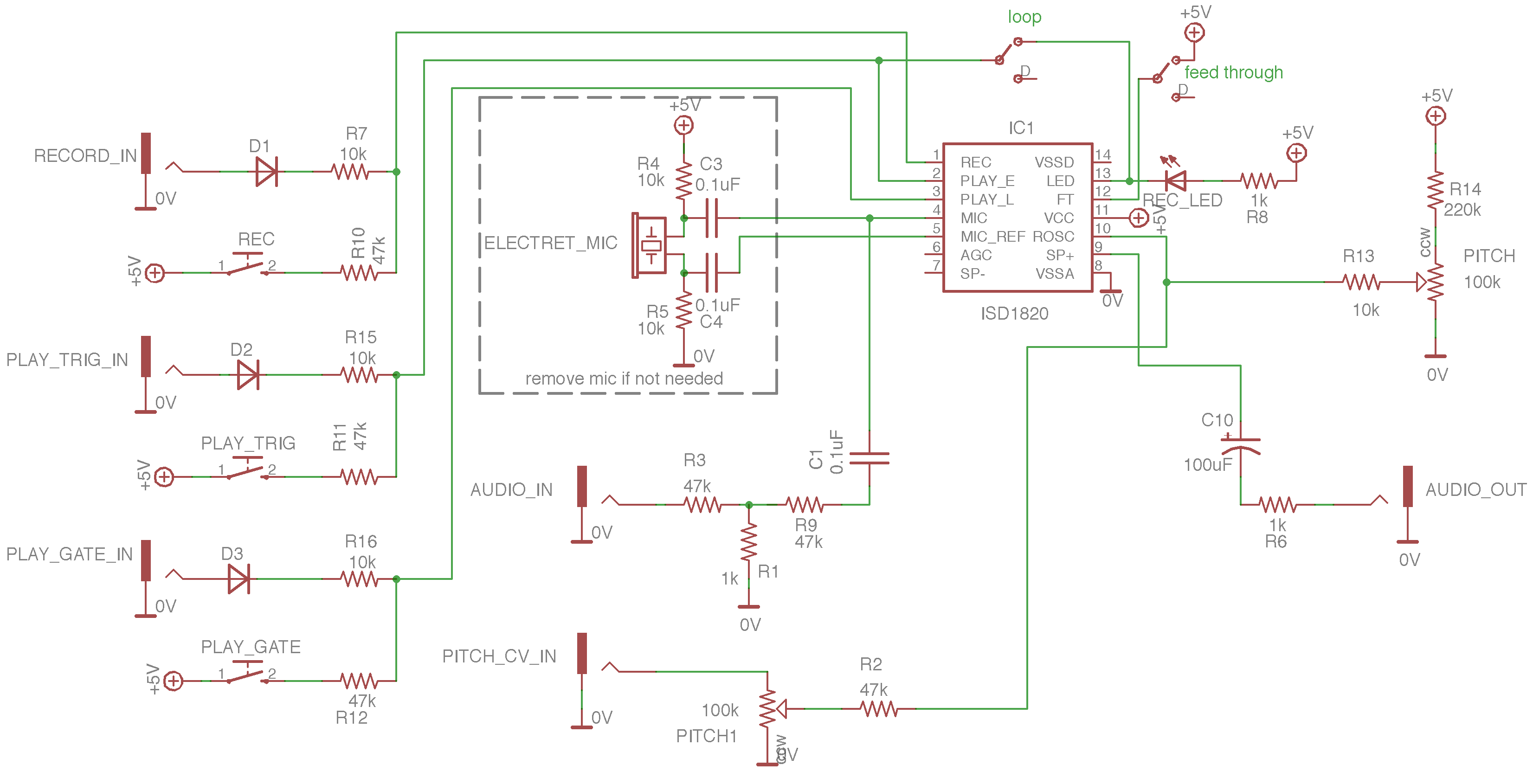
First we’ll start with the most basic sampler circuit. This is taken almost directly from the ISD1820 data sheet. I’ve added:
- extended range on the pitch control
- line in
- stereo headphone output
basic ISD1820 circuit
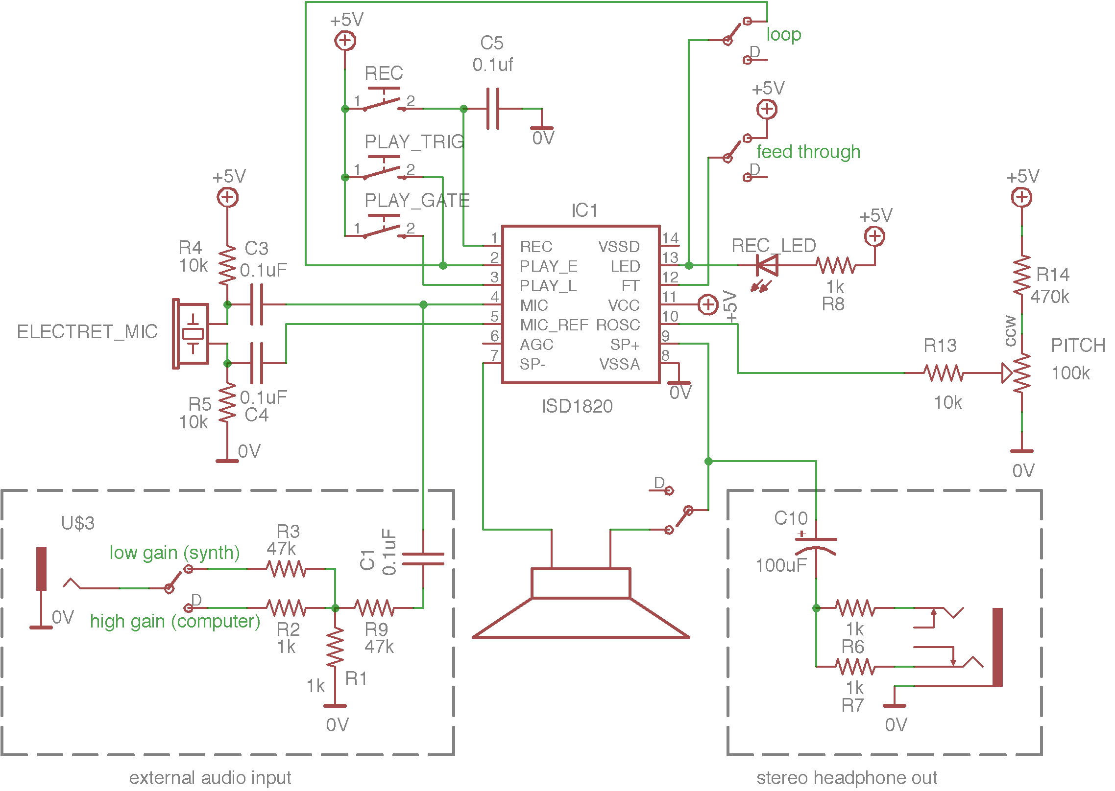
ISD1820
First a note about the ISD1820. This is not a “good” sampler chip… The sound quality is bad, there’s a moment of silence when the sample loops and, most annoyingly, it clicks when the sample starts. These things can’t really be avoided. But despite all this I have found it to be genuinely fun to play with and depending on what you are recording, it can actually be a pretty useful little sampler. Furthermore, this is as cheap and simple as DIY samplers get. I would say this is about as simple as audio circuits in general get, which counts for something. And I’m happy to find that the chip is quite flexible allowing wide pitch control range and modulation options (touch control, CV control, light sensors, potentiometers), and some interesting amplitude control options.
Circuit details:
NOTE ABOUT BUTTONS!
All buttons in this circuit connect a pin on the isd1820 to +5 volts. This is also called setting the pin high. This can be achieved with the button as shown but also with various voltage generators, sequencers, gate dividers etc.
PITCH CONTROL
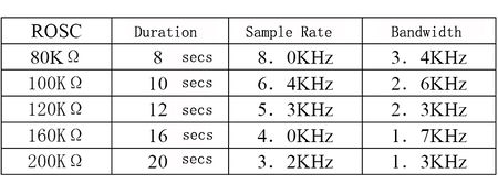
There are several ways to adjust the pitch of this chip. In this schematic I show one of the simplest methods that requires minimal parts and gives you a very wide pitch sweep. R14 determines the low range of the pitch and using 470k gives you about as low a pitch as possible. If you want a higher base pitch, increase this value.
RECORD BUTTON
The chip will record as long as the record input pin is high and until the buffer is full. The length of the recording buffer is dependent on the pitch setting and is rated between 8 and 20 seconds under “normal” settings. At lower pitch the recording time is much longer but the quality is also much lower.
The record feature starts to malfunction at high and low pitch settings! It’s best to do your recording at a middle pitch setting.
C5 on the record button helps “debounce” the signal and minimises false triggers.
PLAY BUTTONS
“Play gate” and “play trig” are two different inputs to play the sample. “Play gate” will play the sample as long as the input to that pin is high (5 volts) “play trig” will run the sample for its duration as soon as it receives 5 volts at the pin, regardless of how long the pulse is. Both are useful but I primarily use the “play trig” input.
REC/SAMPLE END LED
This light is on while the chip is in record mode. It ALSO will flash briefly at the end of playing back a sample.
R8 determines the brightness of the LED.
LOOP SWITCH
The loop switch connects the output of the LED pin to the “play trig” input. That means that at the end of the sample the light will flash. This pulse will also retrigger the sample…making a loop.
FEED THROUGH SWITCH
Setting this pin high passes the input signal to the output but along the way it goes through the chip and is filtered. The Filter cut is determined by the pitch setting. Therefore with a wide pitch range you are able to achieve a nice low pass filter. I go over this in more detail here.
MIC
You can use any ol electret mic for this circuit.
R4,R5,C3 & C4 power and decouple the mic input so it works.
SIGNAL IN
R1,R2, R3, R9 and C1 buffer and attenuate an external signal. It’s necessary to dramatically lower most signals to avoid strong clipping. Use lower value resistors on the input for quieter signals (computer, etc) and higher value for louder ones (modular synth, etc).
HEADPHONE OUT
C10, R6 and R7 make up an output buffer and dual mono signal splitter. This allow you to connect the mono signal from the ISD1820 to a stereo headphone jack. This can also be done by simply connecting the signal to the left and right lugs of the jack. The problem with this is that plugging a mono cable into a stereo jack shorts the left output to ground. So if the signal is connected directly to left and right it will work with headphones but if you plug in a mono jack it will short out the audio signal and you will get no output. The two resistors solve this issue.
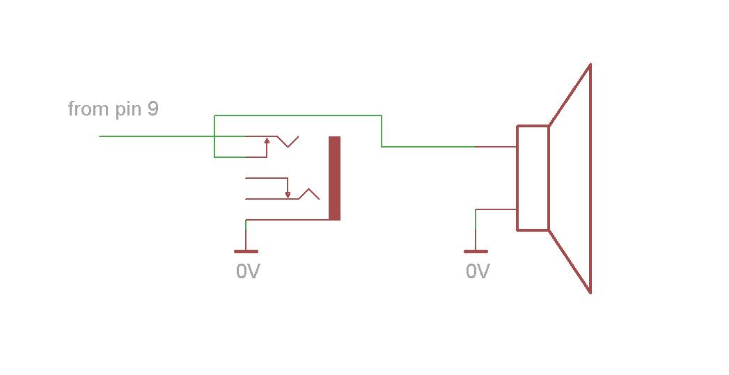
BUT adding these means you can’t add the speaker in series with the jack (common configuration that lets you use the jack as a speaker switch). To do this you can use the schematic below. The downside of this is that you will only get the signal in the right ear of your headphones.
mono output with in-line speaker
ADDING MORE PITCH CONTROL
The ROSC in pin is intended to be connected to ground through a resistor to set the pitch.
That resistor can be easily be replaced or used in parallel with touch and/or light sensors to control the pitch.
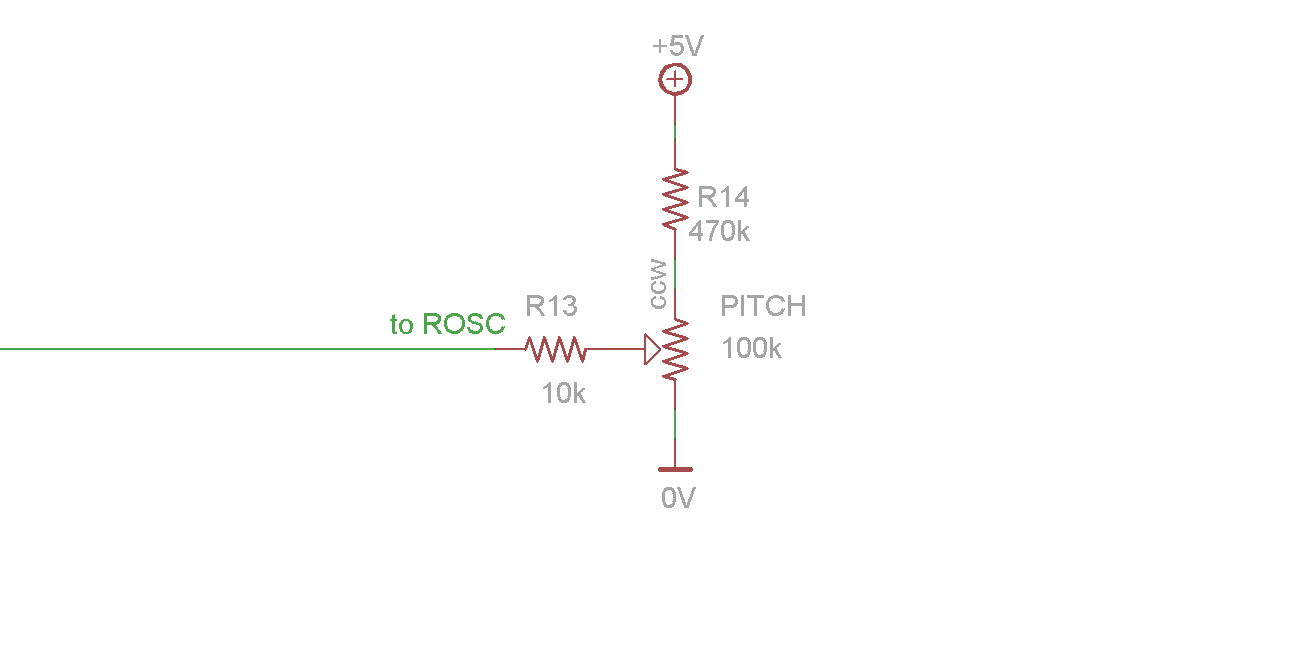
It’s possible to provide a very wide pitch sweep by connecting ROSC to a voltage divider between +&- as shown in the drawing below.
pitch control potentiometer
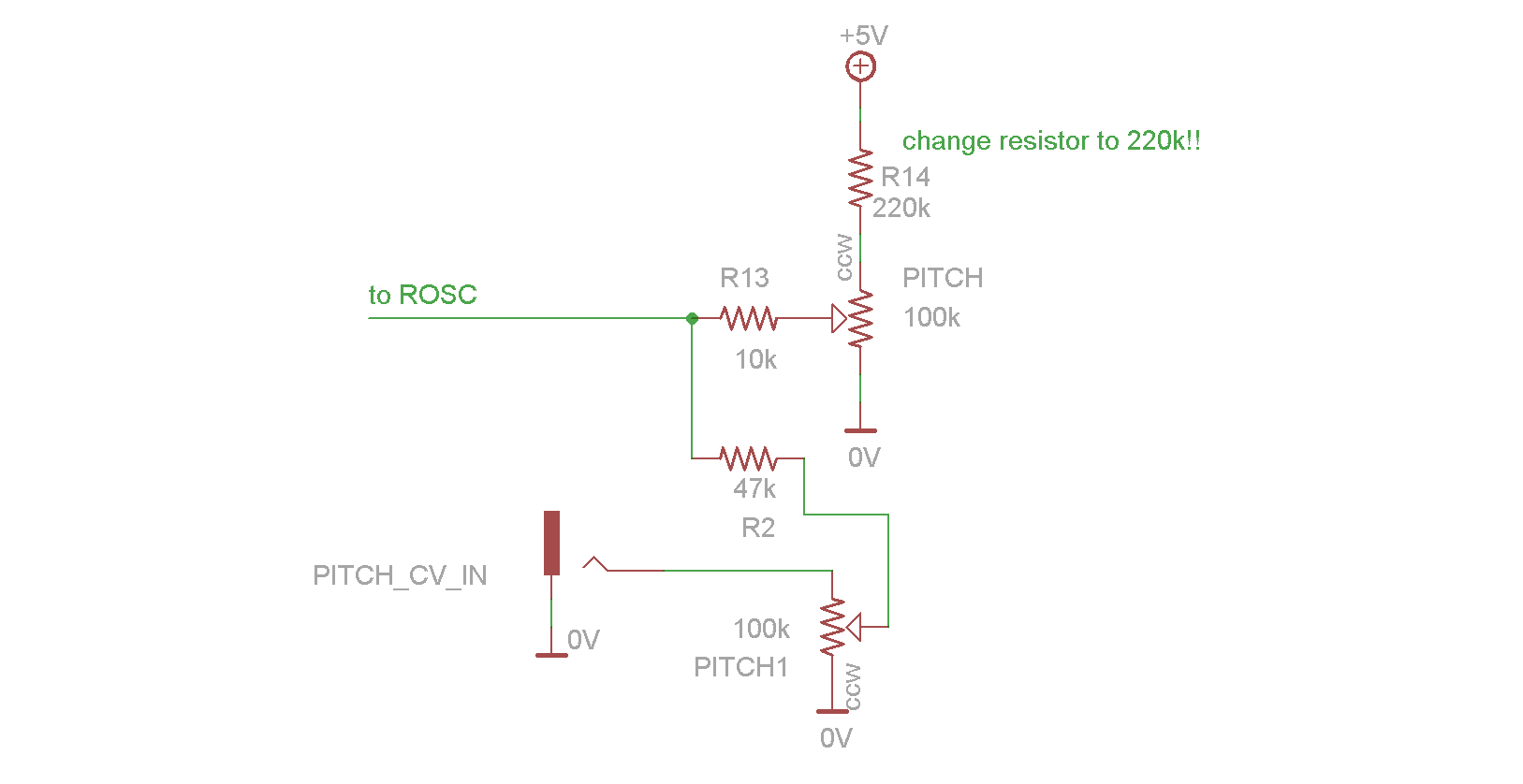
A CV input jack can be added as shown in the picture below. This allows you to interface with modular synthesizers and other electronics.
Modular sampler
Add jacks to interface your sampler with a modular synth!
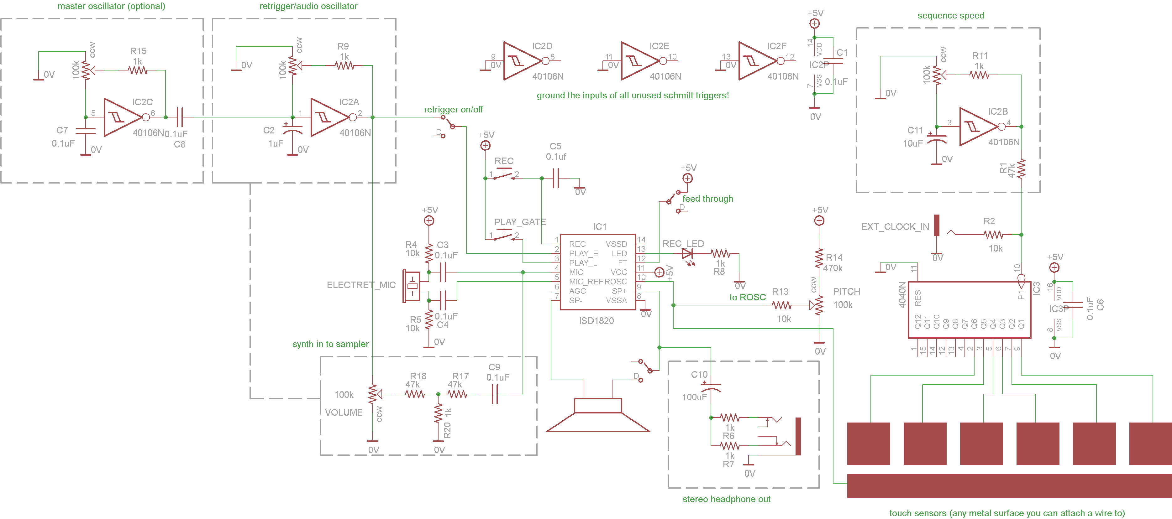
Synth/Sampler
This is the basic sampler circuit above with some extra tricks to allow touch controlled modulation and a built tone generator to record and tweak. One of the coolest things about this version is the touch interface. Each pad is connected to a clock output from a divider. By touching the pitch base (the long strip below the touch pads) and any of the clock pads you can make very interesting rhythmic sequences. The divider can be synced to external gear, but I wanted to keep the circuit simple so there is no buffering. It will work with some (most) devices but not all.